Features
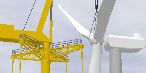
3D Graphics
Highly accurate 3D graphics allow you to view the lift from any angle.
Choose from hundreds of detailed 3D objects to create a realistic rendering of your jobsite.
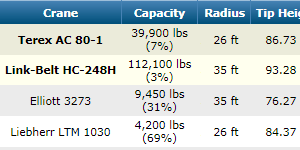
Crane Selection
Search your entire fleet of cranes in seconds.
Any number of obstructions are accounted for whether they are to the side, front, rear, or above the crane.
The most economical crane configurations that can handle your lift are displayed at the top of the results list allowing you to save time sifting though a long list of choices.
Lift Simulation
3D Lift Plan will automatically monitor the crane's capacity while you change the boom angle, jib offset, load location, crane location, or lift radius.
Save snapshots to quickly switch between various points in the lift.
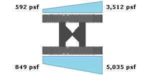
Ground Bearing Pressure
Crawler loads and outrigger loads are automatically calculated, as well as ground bearing pressure below crane mats.
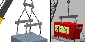
Advanced Rigging Design
Choose from dozens of predefined bridle, choker, basket, and snatch block rigging configurations, or create your own custom design. 3D Lift Plan will calculate your sling angles and tension.
Multiple Crane Lifts
Plan complex multi-crane lifts. As the primary crane moves, the trailing cranes automatically adjust to accurately simulate your lift. The load on each crane is calculated throughout the lift. Tandem and trailing lifts are supported.
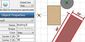
Jobsite Designer
Edit your jobsites in a two-dimensional drag-and-drop environment allowing you to create more complicated lift plans in less time.
Import Images
Import CAD drawings, Google Earth images, or any picture to accurately depict your lift.
Detailed Printouts
Print a 3D rendering of your lift from any angle. Printouts also display the crane and rigging configuration, crane capacity, load details, notes, and your company information.

Share your lift plans
With one click you can share your lift plans with coworkers and clients. You are provided with a URL and they can view your plan in 3D in their web browser.
Critical Lift Worksheet
Print a worksheet for your jobs that includes job information, crane information, and a pre-lift checklist.

Quick Lift Setup
Use our Quick Lift Setup feature to create accurate jobsites quickly by answering a few simple questions.
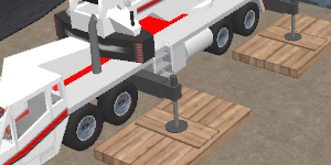
Crane Mats
Enter your steel or wood mat configuration and the ground bearing pressure below the mats and the amount of stress being applied to the mats will be calculated to make sure your design is sufficient.
CAD Export
Export your lift plan in DXF format for use in any CAD program.
Show the area required to assemble the crane
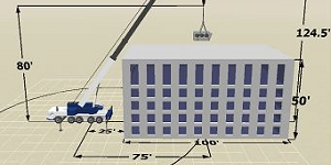
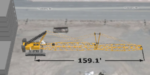
Dimensions
Choose to display common dimensions such as lift radius, load height, and obstructions dimensions, or add custom dimensions to your lift plans.