I-10 Capital Corridor Widening - City Park Lake Bridge
Anthony Saladino, Boh Bros. Construction Co., L.L.C.
The I-10 Capital Corridor project is a Contractor Manager at Risk (CMAR) contract that tasked us with the responsibility of finding the most economical bridge design and method of construction.
Our Joint Venture team of Kiewit/Boh Brothers was chosen for our bridge experience, partnering experience with LADOTD, and ability to provide significant engineering support for our construction methods.
We elected to construct a temporary steel trestle bridge adjacent to the bridge to allow crane access to erect girders.
Before detailed bridge plans were available, I used 3D Lift Plan to create a preliminary model using estimated girder lengths and locations.
The model was used to estimate crane radius and generate bearing pressures for the trestle design.
The preliminary modeling was done in 2022 and influenced the design of the bridge going forward using (2 each) Manitowoc MLC 300 crawler cranes to erect the girders.
Bearing pressures from 3d Lift were used to size the trestle members to properly support the cranes and we began constructing the trestle in 2023 before we were contracted to build the bridge.
As the bridge design progressed, I continually updated the lift plan to further improve its accuracy.
The initial estimations and contingencies were removed, as details were provided, until we had a usable work plan to erect girders.
Lift plan drawings were built in AutoCAD to determine exact crane locations and screen shots from 3D Lift Plan were used to illustrate both the angles and path of the girder during the 2-crane erection sequence.
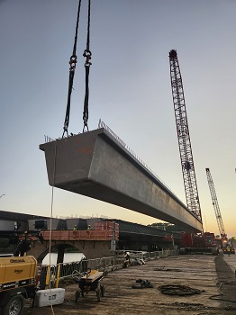
Louisiana Department of Transportation developed a new girder cross section that is a prestressed precast concrete tub girder.
Our project is the first to use the LU girder.
In our case, it decreased the quantity of girders needed, without reducing the span lengths, due to its increased capacity and wider cross section.
The disadvantage of the girder is its increased weight.
This girder has a theoretical weight of 1,530 lbs/lf plus concrete end diaphragms that add approximately 24,000 lbs.
For the approximate length of 145', we anticipated max girder weights of approximately 265,000 lbs.
The trestle access that we constructed allowed unobstructed crane access along the entire length of the bridge.
However, its location is determined by the footprint of the bridge, hence determining the crane's radius.
Careful planning was required to choose the proper cranes early in the process to ensure the capacity of the crane was not exceeded during girder erection.
Early bridge design concepts were used to estimate the radius and girder weights.
A preliminary lift plan was estimated with contingency to ensure our plan would not only succeed but also allow for unforeseen conditions.
Another challenge that needed to be vetted was the size of the trucks delivering the girders - the girder delivery trucks are 200' long by 14' wide due to the girder's heavy weight.
This required a haul lane to be constructed next to the crane path to get within both cranes' allowable radius.
Consequently, the girder would need to be passed in between the cranes.
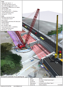
I used 3D Lift software to simulate the challenges of this movement by adjusting crane separation and girder angle while passing the girder in between the cranes, at the same time staying within each crane's minimum and maximum radius.
As access was constructed, better information became available to further detail our plan.
An AutoCAD file was used to incorporate the owner's completed bridge design, our trestle and bulkhead as-builts, and a drone aerial photo.
The collaboration of this data provided more precise positions of the crane and girders.
This file was converted into JPEG file and uploaded to 3D Lift Plan.
The locations from the image were used to build the jobsite and confirm the crane and girder locations.
An additional benefit of the software presented when generating counterweight information for the cranes.
The Manitowoc MLC 300 crane is unique in the fact its counterweights adjust to counteract load moment.
This proved to be incredibly useful information when operating on a confined bridge over water.
Tailswing on this crane increases significantly as loads get heavier which helped our team identify conflicts with the new bridge and other equipment.
The software helped tremendously at the planning stage but, more importantly, provided confidence in the plan as more information was incorporated.
Our lifts were completed successfully due to the large planning effort done, much of which involved the use of 3D Lift Plan.