Tutorial: Outrigger Loads and Crawler Loads
If 3D Lift Plan does not have weight data for your crane, please see the last section of this tutorial to find out how to get it added
to
3D Lift Plan.
3D Lift Plan will automatically calculate outrigger and crawler loads based on the weights and locations of the various parts of the crane,
including the current load and rigging weights. If 3D Lift Plan has weight data for your crane, no further user action is required. Crane
loads will be displayed in the Results section on the Lift Simulation page.
The "Crane Loads" Page
To view outrigger or crawler load details, click the "Crane Loads" link on the left-side menu at any time during the lift-planning process.
Note: The Crane Loads feature is only available if you have a Corporate Account.
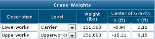
If 3D Lift Plan has crane weight data for your crane, you will see various weights listed in the "Crane Weights" table. You will be notified
if crane weights are not available for your crane, and you can manually enter weights in the "User-Defined Weights" section (see below
for details).

On the right side of the page, you will see the results displayed on an image. For crawler cranes, the bearing length of the track is shown
along with the pressure at each end of the crawlers. For cranes on outriggers, you will see the load on each outrigger.
You can adjust the swing angle from this page by changing the value in the "Swing Angle" text box and pressing the "Update" button. Click
the "Printer-Friendly Page" link to see a page that includes job and crane information. Use your web browser's print function to create
a printout, then press your browser's "Back" button to return to the Crane Loads page.
At this time, the calculations are only valid for cranes on four outriggers or on two crawlers. Results will not be valid if
your crane has a 5th outrigger or a wheeled trailing counterweight.
Manually Adding Crane Weights
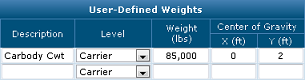
If 3D Lift Plan does not have crane weight data for your crane, or if you would like to account for an additional item attached to your
crane that is not included in the default crane weights, then you can add items to the "User-Defined Weights" table. These items will be
included in the calculations.
You will need to enter the following information for each item...
| A brief description of the item you are adding. |
| The position on the crane so we know how to calculate the location of the item as the crane moves. |
| Use this level if this item does not move when you swing the boom left or right. Examples include the carbody,
crawlers, carbody counterweights, or for truck cranes: the truck or anything attached to the truck. |
| Use this level if the item rotates when you swing the boom left or right, but does not move when you boom up
or down. Examples: upperworks section, counterweights, and boom gantries. |
| Use this level for the boom or any item connected to the boom. |
| Use this level for the jib or any item connected to the jib. |
| The weight of the item. |
The position of the center of gravity (CG) of the item.
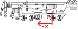
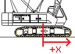 For the Carrier level", the CG is measured relative to the crane’s center line of rotation. +X is toward the front of
the crane or the front of the truck. For truck cranes, the truck’s CG X will typically be a positive value.
For the Carrier level", the CG is measured relative to the crane’s center line of rotation. +X is toward the front of
the crane or the front of the truck. For truck cranes, the truck’s CG X will typically be a positive value.
For the Upperworks level, the CG is measured relative to the crane’s center line of rotation. +X is toward the boom. –X
is toward the counterweight. Most items in the Upperworks level will have a negative value for center-of-gravity X.
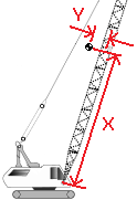 For the Boom level, CG is measured relative to the boom pin. +X is the distance along the length of the boom. +Y is perpendicular
to the boom, measured from the boom centerline.
For the Boom level, CG is measured relative to the boom pin. +X is the distance along the length of the boom. +Y is perpendicular
to the boom, measured from the boom centerline.
For the Jib level, CG is measured relative to the jib’s base pin. +X is the distance along the length of the jib. +Y is
perpendicular to the jib, measured from the jib centerline.
|
On the 3D image, you will see a graphical representation of each crane weight that is being included in the calculations. They are marked
with small spheres representing the center-of-gravity of each item that is listed in the "Crane Weights" or "User-Defined Weights" tables.
This helps ensure that the center-of-gravity locations have been entered correctly. You can enter up to nine custom weights. Only three
rows are shown on the User-Defined Weights table at one time to save space on the screen, but more rows will be available after you enter
some weights and press the Update button.
Adding your crane's weights to 3D Lift Plan
If 3D Lift Plan does not have crane weight data for your crane please contact customer support to request it. It will be very helpful if
you can provide us with crane weights and center-of-gravity information that is usually available from the crane manufacturer upon request.
We need the following information for calculating ground bearing pressure:
Carrier: Weight and center-of-gravity (CG) horizontal distance from the axis of rotation.
Superstructure: Weight, including counterweights, and CG horizontal distance from the axis of rotation.
We'll need this for each possible counterweight configuration, or provide the counterweight data separate from the rest of the superstructure.
Boom: Weight and CG location coordinates for each boom length, including the effects of guy lines, upper
spreader, and boom foot mast.
Jib: Weight and CG location coordinates for each jib length, including the effects of guy lines and jib
mast.
For boom and jib data, the CG locations should be given in terms of a distance along the centerline measured from the
foot pin and an offset above and perpendicular to the centerline.